This unit will give us a chance to look at the physical structure of aircraft. Earlier we built some gliders that were all solid components, but real planes of course have large metal frames and composite hulls. In this unit, we get to learn how Autodesk can be used to create and test aircraft frames. Over the course of the unit, you’re expected to learn the following:
- How to use Autodesk Inventor to create a built-out frame
- How to use Autodesk Inventor to simulate strain on a frame
Computer simulations continue to play an important role in aerospace engineering, because they help us make reasonable estimates about how things will function before we take the time and money to actually build them. In this unit, we’ll spend most of our time in Autodesk, using it as a simulation to test engine mounts:
- STEP 1: Learn how aircraft materials are made, and what various airplane frames look like
- STEP 2: Use Autodesk Inventor to create a potential frame for an airplane engine and simulate a stress test on a similar frame
- STEP 3: Use Autodesk Inventor to create and test a more detailed engine frame
When you’re all done, you will have learned one of the cooler functions of Autodesk Inventor: frame and truss strain analysis. If you’ve had POE, then you’ll recognize some elements of what we work on here!
As we start our learning of engine and airplane frames, we’ll start by looking at some materials. The metals used in frames is made in many different ways, each of which leads to various material properties. Once those processes are chosen, an engineer then needs to design the frame that will make the aircraft itself.
In this part of the unit, you’ll watch a few videos and take some notes on different production processes. You’ll also get a chance to look at aircraft frames and recognize some of the same truss structures you might have seen in POE.
GRADING & PROCESS
![]() Take 1 page of careful notes on metalworking processes
Take 1 page of careful notes on metalworking processes
![]() Take 1 more page of careful notes on aircraft frames and engine mount designs
Take 1 more page of careful notes on aircraft frames and engine mount designs
![]() Have Mr. Benshoof confirm your notes
Have Mr. Benshoof confirm your notes
Metal Working 1
Metal Working 2
Metal Working 3
Aerospace Materials
Materials Properties
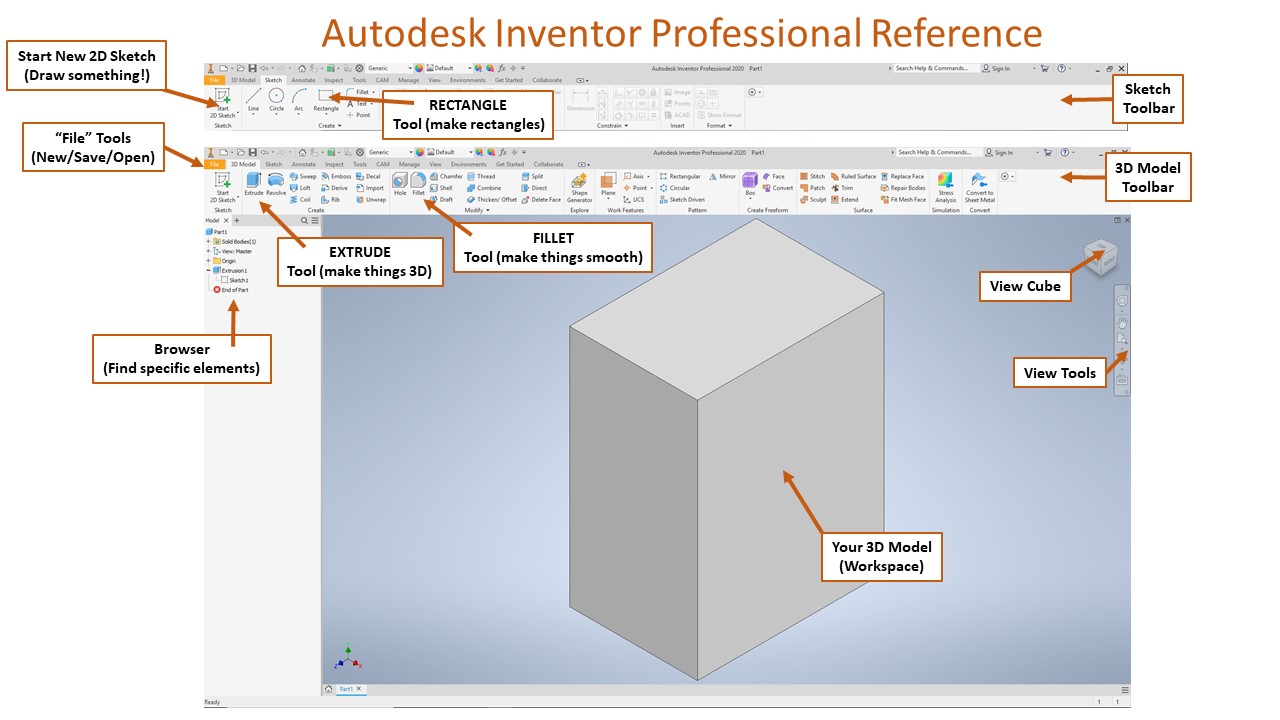
We’ve mentioned many times that a lot of aerospace work happens in computer simulations. This avoids a lot of wasted time, money, and materials building ineffective prototypes. Here, we’ll learn how to use the Frame Generator in Autodesk Inventor to turn a wire model into a 3 dimensional frame model. When this is done, it will be possible to place different loads on the model and see a simulated model of frame deformation and stress.
You’ll first get Autodesk Inventor up and running. Then, it’s a matter of following a series of tutorials very closely to turn the provided wire frame model into an actual engine mount frame. We’ll follow the tutorial step-by-step as we create this first frame. Then a second tutorial will demonstrate how to use the stress analyzer to place loads on a frame and see what happens when the magnitude of those loads changes.
GRADING & PROCESS
![]() Take careful notes on the Autodesk interface and the Frame Generation process
Take careful notes on the Autodesk interface and the Frame Generation process
![]() Follow the tutorial to turn the provided wire frame into the fully built engine mount frame
Follow the tutorial to turn the provided wire frame into the fully built engine mount frame
![]() Have Mr. Benshoof check-off your completed engine frame
Have Mr. Benshoof check-off your completed engine frame
![]() Take careful notes on the Autodesk Stress Analyzer
Take careful notes on the Autodesk Stress Analyzer
![]() Follow the tutorial to analyze the provided frame for various weight
Follow the tutorial to analyze the provided frame for various weight
![]() Have Mr. Benshoof check-off your completed stress analysis
Have Mr. Benshoof check-off your completed stress analysis
Frame Generator Overview
Frame Generator Basics
Stress Analysis
For this last part, you’ll need to apply the process from the last part about how to build a frame and how to analyze various stresses on a potential engine mount. You’ll start with the design brief and downloading the sample wire frame. We’ll do our work with that wire frame initially. If you want to learn how to make your own wire frames, we can do that too!
Starting with the given wire frame, apply your previous experience to build out the frame with the Frame Generator tools. Make sure you use the right materials, joints, and finishes. Then, use the Stress Analysis tools to investigate what happens to the frame with certain forces applied to it.
GRADING & PROCESS
![]() Review your notes on Frame Generation and Stress Analysis tools in Autodesk
Review your notes on Frame Generation and Stress Analysis tools in Autodesk
![]() Use the same processes to build the frame for the engine mount template provided
Use the same processes to build the frame for the engine mount template provided
![]() Continue to do a stress analysis on that completed frame
Continue to do a stress analysis on that completed frame
![]() Consider trying to build your own wire frame and designing your own engine mount!
Consider trying to build your own wire frame and designing your own engine mount!
![]() Have Mr. Benshoof confirm your completed frame & analysis
Have Mr. Benshoof confirm your completed frame & analysis
Part 1 Resources
Part 2 Resources
Part 3 Resources